Arduino and 4 digit 7 segmend led display
The Display I Be Will Using
I will be using SparkFun’s four digit seven display in this circuit. Also follow along with the datasheetand like always if you questions post them in the form below.
The Circuit
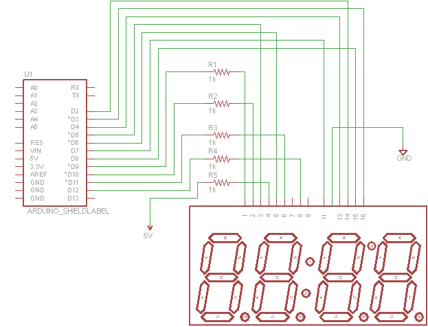
The circuit is pretty straight forward, the clock dots (colon) will be always on, so this circuit is perfect for an alarm clock or any sort of clock. Note that pin 12, after pin 11 but not labeled, is connected directly to ground.

Arduino schematic to control a 4 digit 7 segment display in "clock" mode
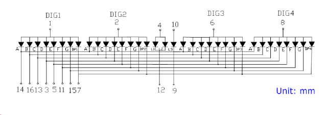
Let’s take a look at the insides of the display to see how to turn on and off the display.

7 segment 4 digit led display insides. The triangles base is the positive side.
Each of the triangles in the image below represents each of the segments in the display, because the digits share the same positive side they can only be turned on through the negative side by setting the pins of the Arduino to zero. In short, the way the circuit is connected a LOW will turn on a segment in the display while a HIGH will turn it off.
Make Variables To Make Code Easier To Understand
Let’s make some variables.
What we should do is make a variable for each digit pin (not segment pin).
int d1=9,d2=10,d3=11,d4=12;
Shorter Code
In a previous tutorial I showed you how to use the register DDRx instead of the function pinMode(), this will make our code more than 10 times shorter. Since all of our pins are outputs we want to set them to ones.
We also want to turn all lights off starting.
void setup()
{
 DDRD=0xff; // all pins 0-7 OUTPUTs
 DDRB=0xff; // all pins 8-13 OUTPUTs even though we only use pins 8-12
 PORTD=0x00; // make pins 0-7 LOWs
 PORTB=0x00; // make pins 8-13 LOWs
}
How Do You Display Different Numbers When All Segments Are Connected?
Since all the segments of each digit share the same ground connection what we need to is the following.
- Turn on first digit, turn off all other digits
- Turn on segments we need for first digit
- Turn off all digits, turn on second digit
- Turn on segments we need for second digit
- Turn off all digits, turn on third digit
- Turn on segment we need for third digit
- Turn off all digits, turn on fourth digit
- Turn on all segments we need for fourth digit
Since this is happening very very fast you won’t even see any digits turn off but they will different numbers. A delay of 2 milliseconds was implemented to give the digits and segments enough time to turn off before the next is displayed.
So our code is this.
void loop()
{
  // light up first digit only
  digitalWrite(d2,LOW);
  digitalWrite(d3,LOW);
  digitalWrite(d4,LOW);
  digitalWrite(d1,HIGH);
    // light up segments of first digit, display number #1, segments bc
    PORTD=B11100111; //B00011000; // only pins 2 and 3 are on
    digitalWrite(8,HIGH); // turn off pin 8
delay(2);
  // light up second digit only
  digitalWrite(d1,LOW);
  digitalWrite(d3,LOW);
  digitalWrite(d4,LOW);
  digitalWrite(d2,HIGH);
    // light up segments of second digit, display #2, segments abdeg
    PORTD=B10010011; //B01101100; // only pins 2,3,5 and 6 on
    digitalWrite(8,LOW); // segment g on
delay(2);
  // light up third digit only
  digitalWrite(d1,LOW);
  digitalWrite(d2,LOW);
  digitalWrite(d4,LOW);
  digitalWrite(d3,HIGH);
    // light up segments of third digit, display #3
    PORTD=B11000011; //B00111100; // only pins 2,3 and 5 on
    digitalWrite(8,LOW); // segment g on
delay(2);
  // light up fourth digit only
  digitalWrite(d1,LOW);
  digitalWrite(d2,LOW);
  digitalWrite(d3,LOW);
  digitalWrite(d4,HIGH);
    // light up segments of fourth digit only, display #4
    PORTD=B01100111; //B10011000; // only pins 3,4 and 7 on
    digitalWrite(8,LOW); // segment g on
delay(2);
}
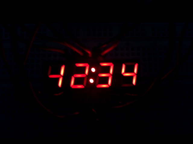
What would happen if the delay was not implemented? Check out the picture below, notice how you can see (barely) the previous digit in the next one.

4 digit 7 segment without a delay, notice the numbers are overlapping.
The Full Code
If you just hate typing here’s the code put together.
int d1=9,d2=10,d3=11,d4=12;
void setup()
{
 DDRD=0xff; // all pins 0-7 OUTPUTs
 DDRB=0xff; // all pins 8-13 OUTPUTs even though we only use pins 8-12
 PORTD=0x00; // make pins 0-7 LOWs
 PORTB=0x00; // make pins 8-13 LOWs
}

void loop()
{
  // light up first digit only
  digitalWrite(d2,LOW);
  digitalWrite(d3,LOW);
  digitalWrite(d4,LOW);
  digitalWrite(d1,HIGH);
    // light up segments of first digit, display number #1, segments bc
    PORTD=B11100111; //B00011000; // only pins 2 and 3 are on
    digitalWrite(8,HIGH); // turn off pin 8
delay(2);
  // light up second digit only
  digitalWrite(d1,LOW);
  digitalWrite(d3,LOW);
  digitalWrite(d4,LOW);
  digitalWrite(d2,HIGH);
    // light up segments of second digit, display #2, segments abdeg
    PORTD=B10010011; //B01101100; // only pins 2,3,5 and 6 on
    digitalWrite(8,LOW); // segment g on
delay(2);
  // light up third digit only
  digitalWrite(d1,LOW);
  digitalWrite(d2,LOW);
  digitalWrite(d4,LOW);
  digitalWrite(d3,HIGH);
    // light up segments of third digit, display #3
    PORTD=B11000011; //B00111100; // only pins 2,3 and 5 on
    digitalWrite(8,LOW); // segment g on
delay(2);
  // light up fourth digit only
  digitalWrite(d1,LOW);
  digitalWrite(d2,LOW);
  digitalWrite(d3,LOW);
  digitalWrite(d4,HIGH);
    // light up segments of fourth digit only, display #4
    PORTD=B01100111; //B10011000; // only pins 3,4 and 7 on
    digitalWrite(8,LOW); // segment g on
delay(2);
}
Functions To Make Your Life Easier
This is the type of project where functions come in handy, let’s add two function to our code one to turn on a certain digit, we will call each digit a square, and the other one to turn on a certain number in our display.
Function For Each Square
This function will turn on one digit but turn off the rest.
void turnOnSquare(int num)
{
int d1=9,d2=10,d3=11,d4=12;
 switch(num)
 {
   case 1:
    digitalWrite(d2,LOW);
    digitalWrite(d3,LOW);
    digitalWrite(d4,LOW);
    digitalWrite(d1,HIGH);
   break;
   case 2:
    digitalWrite(d1,LOW);
    digitalWrite(d3,LOW);
    digitalWrite(d4,LOW);
    digitalWrite(d2,HIGH);
   break;
   case 3:
    digitalWrite(d1,LOW);
    digitalWrite(d2,LOW);
    digitalWrite(d4,LOW);
    digitalWrite(d3,HIGH);
   break;
   case 4:
    digitalWrite(d1,LOW);
    digitalWrite(d2,LOW);
    digitalWrite(d3,LOW);
    digitalWrite(d4,HIGH);
   break;
   default:
   // this should never occur, but do what you want here
   break;
 }

}
Function For Each Number
void displayDigit(int num)
{
   switch(num)
   {
     case 0:
      PORTD=B00000011; // pins 2-7 on
      digitalWrite(8,HIGH); // turn off pin 8
     break;
     case 1:
      PORTD=B11100111; // only pins 2 and 3 are on
      digitalWrite(8,HIGH); // turn off pin 8
     break;
     case 2:
      PORTD=B10010011; // only pins 2,3,5 and 6 on
      digitalWrite(8,LOW); // segment g on
     break;
     case 3:
      PORTD=B11000011; // only pins 2,3,4 and 5 on
      digitalWrite(8,LOW); // segment g on
     break;
     case 4:
      PORTD=B01100111; // only pins 3,4 and 7 on
      digitalWrite(8,LOW); // segment g on
     break;
     case 5:
      PORTD=B01001011; //B10110100; // only pins 2,4,5 and 7 on
      digitalWrite(8,LOW); // segment g on
     break;
     case 6:
      PORTD=B00001011; //B11110100; // only pins 2,4,5,6 and 7 on
      digitalWrite(8,LOW); // segment g on
     break;
     case 7:
      PORTD=B11100011; // only pins 2,3 and 4 on
      digitalWrite(8,HIGH); // segment g off
     break;
     case 8:
      PORTD=B00000011; // pins 2-7 on
      digitalWrite(8,LOW); // turn on pin 8
     break;
     case 9:
      PORTD=B01000011; // only pins 2,3, 4 and 5 on
      digitalWrite(8,LOW); // segment g on
     break;
   }
}
Example Usage Of Functions
Add the functions above and the code below to a new sketch and run it. The display should show the numbers 0-9 and repeat.
int i=0;

void setup()
{
 DDRD=0xff; // all pins 0-7 OUTPUTs
 DDRB=0xff; // all pins 8-13 OUTPUTs even though we only use pins 8-12
 PORTD=0x00; // make pins 0-7 LOWs
 PORTB=0x00; // make pins 8-13 LOWs
}

void loop()
{

  for(i=0;i<=9;i++)
  {
  turnOnSquare(1);
  displayDigit(i);
  delay(1000);
  turnOnSquare(2);
  displayDigit(++i);
  delay(1000);
  turnOnSquare(3);
  displayDigit(++i);
  delay(1000);
  turnOnSquare(4);
  displayDigit(++i);
  delay(1000);
  }

}
// paste the two functions after this line.
What could we do to improve our code or circuit? leave your comments below.
