Now that you know how to turn and how to flash on and off an led you are ready to turn on multiple LEDs. More precisely you are ready to make an automatic counter.
For this tutorial you will need a 7 segment indicator. I recommend that you get the one I got but you don’t have to if you know what am doing.
Like always; watch the video below to see the result and scroll down to learn to do it.
Circuit Design
Before we start connecting wires here and there we have to think about what what we have, what it is that we want and plan it out.
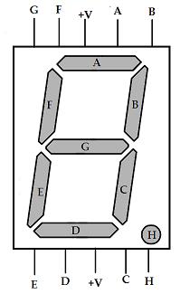
What I have here is a 7 segment led, each of the segments will be controlled by a different pin in the board, we don’t have to use both of the power pins so I’ll use the top one and connect that one to the 5 volt pin in the board; I have named each segment and connection as in the picture below.

7 Segment Indicator All Lights Off
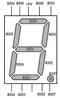
Now I need to control each of those segments with pins from the PIC18 board, so I will rename each segment with the pin with which I want to control it; I have chosen to use all of port H. So my new picture is below.

7 Segment LED Indicator Renamed
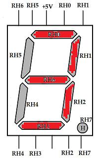
Now the way my circuit will be wired, as you’ll see below in a moment, if I want to display a number I will have to set the ports used by that number to zero. For example if I want to show the number three I will have to set the ports RH0 RH1 RH2 RH3 and RH6 to zero, all my other pins will be set to one.

7 Segment LED Indicator Showing the Number 3
Circuit Wiring
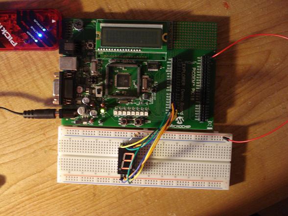
For this part just follow the picture of the 7 segment indicators and connect each pin from the indicator to the pin in the board. The pin in the middle at the top will be connected to a resistor and the 5 volts pin in the board.

7 segment counter all wired up
The Software: Everybody Loves Binary Numbers
If you have read all of my previous tutorials you will notice that to refer to a pin in my PIC18 board I have been using the following notation. For example to set pin RB5 to 0 I would use.
PORTBbits.RB5=0;
Now imagine having to turn on the number 3, no don’t imagine it, here is the code that would do that.
PORTBbits.RB0=0;
PORTBbits.RB1=0;
PORTBbits.RB2=0;
PORTBbits.RB3=0;
PORTBbits.RB4=1;
PORTBbits.RB5=1;
PORTBbits.RB6=0;
PORTBbits.RB7=1;
Now you are thinking, "well I’ll just copy and past&qout;. Scratch that off your list, we’ll use an easier, faster notation: binary. Don’t be scared though, you don’t really have to know binary, just continue reading.
In binary notation if I want to show the number three in board all I’ll have to do is the following.
PORTB=0b10110000;
where the number after "0b" is a binary number that represents each of the RB ports; the count starts at the right from RH0 and ends to the right of "0b" with RH7. That wasn’t hard at all was it? perhaps looking at the whole code will help.
#include <p18f8722.h> // include the respective pic file
#include <delays.h>
#pragma config OSC=HS // high speed oscillator
#pragma config WDT=OFF // watch dog off
void main ()
{
	TRISH = 0; // set E ports to be outputs

	while(1)
	{
		Delay10KTCYx(0);
		PORTH=0b11000000; // 0
		Delay10KTCYx(0);
		PORTH=0b11111001; // 1
		Delay10KTCYx(0);
		PORTH=0b10100100; // 2
		Delay10KTCYx(0);
		PORTH=0b10110000; // 3
		Delay10KTCYx(0);
		PORTH=0b10011001; // 4
		Delay10KTCYx(0);
		PORTH=0b10010010; // 5
		Delay10KTCYx(0);
		PORTH=0b10000010; // 6
		Delay10KTCYx(0);
		PORTH=0b11111000; // 7
		Delay10KTCYx(0);
		PORTH=0b10000000; // 8
		Delay10KTCYx(0);
		PORTH=0b10011000; // 9
	}
}
Notice that I’ve added a delay before showing each number, this is so that you are able to see it change. Feel free to add more delays if you want to slow it down.
The Software (again): Everybody Loves Hexadecimal Numbers
In the previous code you can also replace the value of the ports with hex numbers instead of binary. All you have to do is change the "0b" to "0x" and the number after it to hexadecimal. This can be done manually, it’s really easy and I’ll show later, but you can also a cheap calculator that has this function.
Here is the new code.
#include <p18f8722.h>
#include <delays.h>
#pragma config OSC=HS // high speed oscillator
#pragma config WDT=OFF // watch dog off
void main ()
{

	TRISH = 0; // set E ports to be outputs

	while(1)
	{
		Delay10KTCYx(0);
		PORTH=0xC0; // 0
		Delay10KTCYx(0);
		PORTH=0xf9; // 1
		Delay10KTCYx(0);
		PORTH=0xa4; // 2
		Delay10KTCYx(0);
		PORTH=0xb0; // 3
		Delay10KTCYx(0);
		PORTH=0x99; // 4
		Delay10KTCYx(0);
		PORTH=0x92; // 5
		Delay10KTCYx(0);
		PORTH=0x82; // 6
		Delay10KTCYx(0);
		PORTH=0xf8; // 7
		Delay10KTCYx(0);
		PORTH=0x080; // 8
		Delay10KTCYx(0);
		PORTH=0x98; // 9
	}
}
