Welcome to the first of many tutorial on how to use your PIC18 Explorer Board. If you don’t have one yet you can get one from microchip.com, be sure to sign up with your student email if you have one so you can get a 25% discount.

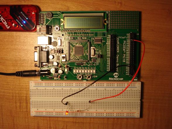
The PIC explorer board and lit up LED
The Circuit
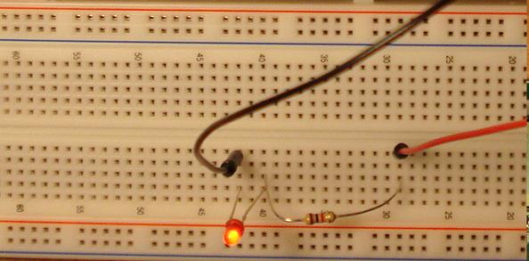
The circuit consists of 1k resistor and a red LED.

An LED connected to a 1k resistor
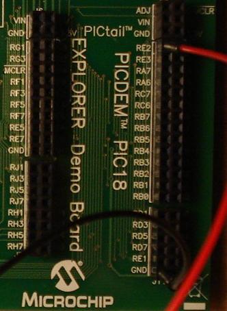
The positive side of the LED is connected to port RE2 of the board. The other side is connected to the ground pin (GND) of the board.

RE2 and ground pins
The Software
The board can be programmed with any language for which there is compiler for PICs, I’ll be using C for these tutorials. If you haven’t programmed in any language don’t worry, I’ll try to do my best to walk you through it, but be sure to check out my programming tutorials coming up soon.
I should also note that am using Microchip’s MCC18 compiler, which has a free version and that’s what am using.
Here is the code.
#include <p18f8722.h> // include the respective pic file
#pragma config OSC=HS // high speed oscillator
#pragma config WDT=OFF // watch dog off
void main ()
{
	PORTEbits.RE2=1; // set port RE2 to 1
	TRISE = 0x00; // set E ports to be outputs
	while(1); // repeat this
}
Alright so let me explain the code line by line.
#include <p18f8722.h>
In this first line I’ve included the library for the PIC am programming. Since we are using the board’s PIC18F8722 microcontroller we included the file p18f8722.
void main()
Every program you write is going to have one this one. If you have programmed in any other language you will recognize that main() is a function. The word void simply means that the function does not return anything.
If you are brand new to programming just remember that every program you write needs this line for now.
{
This just means that this is where the main() function begins.
PORTEbits.RE2=1; // set port RE2 to 1
With this line we tell the PIC that we are setting the value of pin RE2 to 1, we’ll give this 1 a meaning with the next line. Everything to the right of the double backslash is a comment and is ignored by the compiler.
TRISE = 0; // set E ports to be outputs
With this line we are telling the microcontroller that all the E ports; RE0, RE1, RE2 etc are going to be used as outputs. We can also use hexadecimal ( 0x00) or binary numbers (0b00000000) for the values of TRISE; more on that in later tutorials.
while(1);
This is called a while loop and is used to repeat a set of instructions over and over again until the condition inside the parenthesis is false. The way microcontrollers work is they’ll repeat the whole program over and over gain when we supply power, but we don’t have to repeat the whole thing over and over, that would mean that is has to load libraries and initialize variables (which we will later have ) again and again, so we just tell it to stay in this line.
}
Closes the main() function and we are done!
