The potentiometer in a PIC18 Explorer Board
The Program We’ll Be Writing
We will write a program that will read the voltage at the potentiometer and we will display that voltage using the LEDs in port D.
The Potentiometer
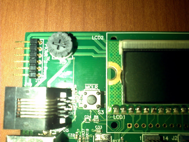
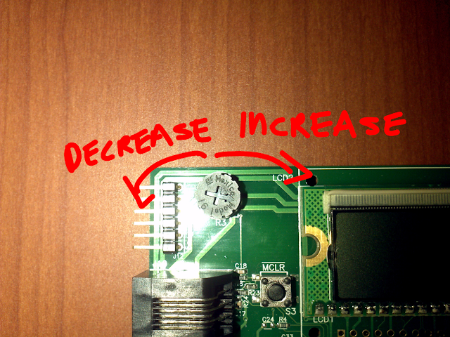
The potentiometer is the wheel to the left of the LCD, it is connected to RA0. Turning the potentiometer to the right increases the voltage at RA0, turning it left decreases the voltage.

turning it right increases input voltage, turning it left decreases it
The Data We’ll Receive
The data we are reading is a binary representation of the voltage at the pot (RA0), more precisely it is a 10 bit binary number, actually split into two (uneven) sections: the most significant and least significant bits. We will only be using the most significant bits which will be eight ( the least significant bits are 2)
If all the bits are 1 we have the highest possible voltage ( ideally 5.0V) all bits zero will mean 0.0V (ideally).
// example
0b00000000; // will be least voltage
0b11111111; // will be max voltage
any other binary number in between is a voltage between 0V and 5V.
Configure The Ports
Since the pot is located at port A we will make port A an input; port D will be an output.
	TRISA=0xff; // port A input
	TRISD=0x00; // port D output
Configuring The A/D Module
There are three bit sets you need to configure ADCON0, ADCON1 and ADCON2, each bit set has eight bits.
ADCON0 Configuration
The first two most significant bits (from left to write) are unimplemented so we can leave them as zeros.
ADCON0=0b00
The next four let you choose the channel want to use, since the potentiometer is connected to AN0 we will make all the four bits zeros.
ADCON0=0b000000
The next bit let’s you start the analog to digital conversion, in other words when ever you give it a value of 1 it will start reading the voltage, we are not there yet so make a zero.
ADCON0=0b0000000
Lastly we want to turn on the analog to digital module
ADCON0=0b00000001;
You can read page 270 of the datasheet to see all the available options.
ADCON1 Configuration
Similarly for ADCON1 one we have (from left to right) the first two bits which are unimplemented.
ADCON1=0b00
The next two represent your reference voltage. I’ll be using AVDD and AVSS so my bits are all zeros
ADCON1=0b0000
The next four bits let you select which ports you want to be analog and which digital. We can use several codes since we need AN0 to be analog and we are not worried about the rest, so I’ll be using all zeros
ADCON1=0b00000000;
Check page 271 of the datasheet to see all options that are available.
ADCON2 Configuration
This is the last bit set we need to configure before we start the conversion.
The first bit lets you select the justification of your result (left of right), we want left so ours is 0;
ADCON2=0b0
The next bit is unimplemented so make it zero as well
ADCON2=0b00
Next three bits are to set the time acquisition delay, there are several options (check page 272 of the datasheet) we want to go with 0 TAD so we have all zeros.
ADCON2=0b00000
The last three bits set the oscillator, we are going with FOSC/32 so we need a two (in binary)
ADCON2=0b00000010;
Starting The Conversion and Reading the Result
Setting the GO_DONE bit of ADCON0 to 1 will start the conversion, GO_DONE will change to zero when the conversion is finished. The result of the conversion is store in ADRESH and ADRESL, most significant and least significant bits respectively.
So here is what we need
ADCON0bits.GO_DONE=1; // starts conversion
while(ADCON0bits.GO_DONE==1); // wait, it's converting
PORTD=ADRESH; // turn on lights, this is outside of the while loop
The Complete Code
Putting everything together we end up with this program.
#include <p18f8722.h>

#pragma config OSC=HS // high speed oscillator
#pragma config WDT=OFF // watch dog off

void main()
{

	TRISA=0xff; // port A input
	TRISD=0x00; // port D output
	PORTD=0x00; // port lights off
	PORTA=0x00;

	MEMCONbits.EBDIS=1; // make port d digital

	ADCON0=0b00000001;
	// (00) unimplemented (0000) channel AN0 (0)don't start yet (1) turn on analog to digital module, see page 270

	ADCON1=0b00000000;
	// (00) unimplemented (00) using AVDD and AVSS (0000) A/D port bits, see page 271

	ADCON2=0b00000010;
	 // (0) left justified (0) unimplemented (000) 0 TAD (010) FOSC/32, see page 272

	while(1)
	{
		ADCON0bits.GO_DONE=1; // starts conversion
		while(ADCON0bits.GO_DONE==1); // wait, it's converting

		PORTD=ADRESH; // this is outise of the while loop

	}
}
