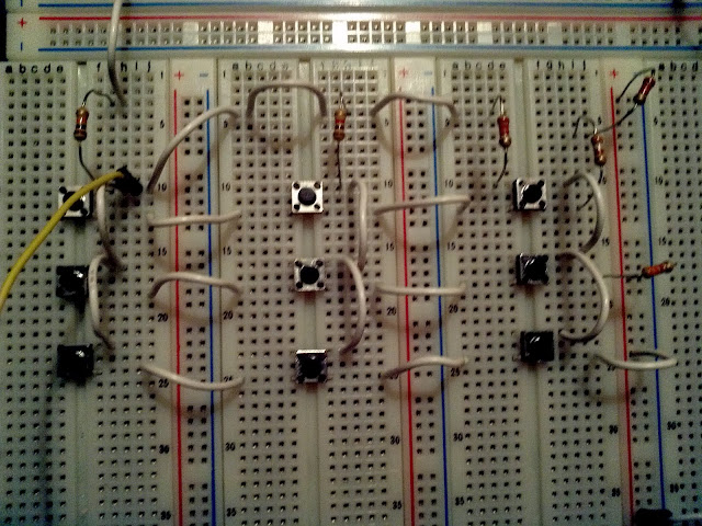
3x3 keypad circuit in breadboard
What can you do with a bunch of buttons and a few resistors? How about a keypad for your next microcontroller project.
Keypad Schematic and Explanation
The following is a 3×3 keypad that could easily be extended to more keys, when a button is pressed the resistors in that button’s column and row form a voltage divider with the 10k resistor below. The cool thing about this keypad is that it would only require one pin of a micronctroller.

schematic of the 3x3 keypad
The output (Vout) is taken at the 10k resistor. The output can then be fed to a microcontroller A/D or any other circuit that can read different voltages, because each button produces a unique combination of resistors the output will be different for every button.
In my original design I had a 6k and 2k resistors, these were replaced with 3.9K and 2.2k and 2.2k respectively because I did not have 6k nor 2k in my resistor box. A picture of the circuit in real life is shown below.

keypad circuit in breadboard. The picture was taken sideways, from left to right and top to bottom the keys are 7,4,1;8,5,2;9,6,3
Keypad Output Table
Using a 10bit A/D converter the output of this keypad is the following.
| Key | Bit Value In Decimal | Analog (V) | Analog Expected(V) |
|---|---|---|---|
| 1 | 554-556 | 2.71-2.77 | 2.7322 |
| 2 | 650-662 | 3.18-3.24 | 3.23 |
| 3 | 835-840 | 4.08-4.11 | 4.10 |
| 4 | 595-602 | 2.91-2.94 | 2.92 |
| 5 | 711-716 | 3.48-3.50 | 3.50 |
| 6 | 929-931 | 4.54-4.55 | 4.55 |
| 7 | 631-637 | 3.08-3.11 | 3.11 |
| 8 | 766-770 | 3.74-3.76 | 3.76 |
| 9 | 1023 | 5.0 | 5.0 |
Note that because the resistors actual value vary so does the output but they still fall within a range that is different for each button. The bit value to analog conversion was done using the formula
[VoltageSource/(2^numberOfBitsOfA/D)]*BitValueOfKey=Analog
In our circuit the formula,assuming a 10 bit A/D converter, translates to
[5V/(2^10)]*BitValueOfKey=Analog
The expected analog value was calculated using the voltage divider formula for each button where
Vbutton=VSource*10k/(Rrow+Rcolumn+10k)
Possible Microcontroller Implementation
If you want to implement this keypad in a microcontroller connect its output to an analog pin of the micro and use the following conditions in a function to differentiate the keys, note that I left more margin for possible errors from the readings above.
  if(voltage>=550 && voltage<=570)
  return 1;
  else if(voltage>=645 && voltage<670)
  return 2;
  else if(voltage>=830 && voltage<=845)
  return 3;
  else if(voltage>=590 && voltage<=610)
  return 4;
  else if(voltage>=700 && voltage<=725)
  return 5;
  else if(voltage>=920 && voltage<=940)
  return 6;
  else if(voltage>=620 && voltage<=640)
  return 7;
  else if(voltage>=760 && voltage<=775)
  return 8;
  else if(voltage>=1000 && voltage<=1023)
  return 9;
How can we improve this circuit? leave your comments or questions below.
