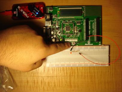
There are lots of things that you can do with your PIC18 board using only outputs, but we can do far more if we add inputs to your code. In this post I’ll show you how to use your board’s RB0 button to turn on a red LED, simple? yes, but this will be the starting point of more complex projects to come.
Watch the video of the result then scroll down to learn to do it.
The Circuit
Connect RH0 to the resistor and anode of the LED. Now connect the other side to ground.

pic18 and led connection.
The Code: Inputs and Outputs
To let the microcontroller know that we are going to use PORTB as an input we have to give TRISB a value of one. When the button (RB0) is pressed its value will go to zero (yes zero, not one) so we will check RB0 in an if statement; if RB0 is equal to zero we’ll turn on the LED else we’ll turn it off.
#include <p18f8722.h> // include the respective pic file
#pragma config OSC=HS // high speed oscillator
#pragma config WDT=OFF // watch dog off
void main ()
{
	TRISB=1; // port b as inputs
	TRISH=0; // port h as ouputs

	while(1)
	{
		if(PORTBbits.RB0==0)
			PORTHbits.RH0=1;// light on
		else
			PORTHbits.RH0=0;// light off
	}
}
