In this post I will walk you through the steps required to program an AVR chip using the AVRISP mkII.

AVR chip, programmer, adapter, breadboard and power supply
Hardware and Software Required
Here is a list of things you’ll need
Hardware
- 4.7K resistor
- 1k resistor
- LED
- AVR Chip: I’ll use the atmega328p
- Programmer: AVRISP mkII
- AVR Programmer Adapter (optional)
- Jumper Wires
- 5V Power supply. You can of course use batteries if you prefer.
Software
Circuit Set Up
Simply find the pins in your programmer, match them to the pins in your chip and connect them. Also connect the resistor from pin 7 to power.
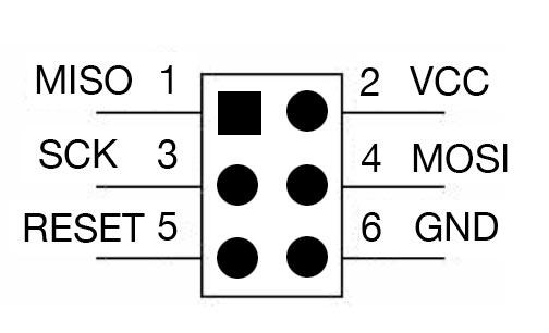
AVRISP MKII pins

ATmega328p pin out
Now because the programmer doesn’t have one squared hole, or at least mine doesn’t, it has many, let me show how how that looks in real life, and yes it is like a mirror image of the image above (weird right?).
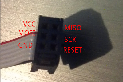
AVRisp mkII holes
Now that we have everything connected…

AVRISP mkII: circuit to program
..let’s move on to the software. Check out the picture at the very top of this page to see how much neater your circuit will be with the programming adapter.
Your First AVR Program
Let me go ahead and walk you through the steps of using AVR Studio 5.
Once you have opened AVR Studio click on File ->New -> Project.
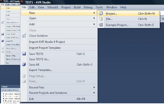
Creating a new project in AVR Stduio 5
Name your project, I named mine firstprogram. Now click the OK button.

naming your project
Next you will be greeted with an almost blank C file.
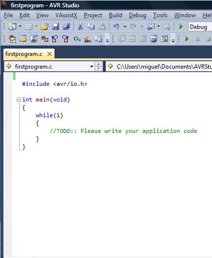
AVR Studio blank template C file
So what software are we going to write? how about we make an led blinker. Connect an LED to port C5 of your microcontroller through the 1k resistor and then to ground.

red led connected to port C5 (pin 28) of the ATmega328p
Now back to AVR Studio. Replace the text in the file with the following.
#include <avr/io.h>
#include <avr/delay.h> // has some delay functions you can use

int main(void)
{
	DDRC=0xff; // all C ports as output
    while(1)
    {
        //TODO:: Please write your application code

		PORTC=0xff; // turn on all C porst
		_delay_ms(200); // wait 200 milliseconds
		PORTC=0x00; // turn off all c ports
		_delay_ms(200); // wait 200 milliseconds


    }
}
The code that gets uploaded to the microcontroller is actually a HEX file, but we have to tell AVR Studio to make this file. To do that right click on your project’s name on the right in the solution explorer window and click on properties.

AVR studio solution explorer window
In the new window that will open check the box that says hex and save (CTRL+S)

hex file checkbox, make sure it's checked.
Now to actually generate the hex file click Build->Build Solution
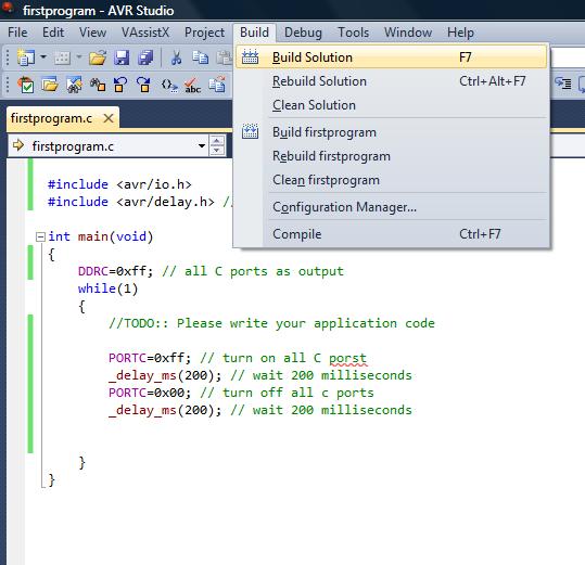
this will compile the program and generate the hex file we need.
You should not get any errors, as shown below.

no compilation errors
Upload The Code to The Microcontroller
At last, we are done with all the software developing stuff, uploading is just as easy.
Click on Tools->AVR Programming
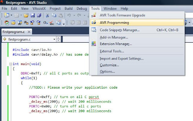
avr studio tools menu
You’ll get the programming window. Make sure that your device is selected.

the programming window
Now in the following order, click on the Apply button, then the voltage button (recycling/refresh looking icon) will become active now click it, you should get some value close to 5 volts. Then click on the Read button. If you didn’t get any error window you are good to go.
Clicking the Read and Voltage buttons is not necessary actually, but the Apply button is.

programming window after clicking buttons
lastly click on Memories and select your hex file then click Program, the programmer will start blinking and stop when your program is done uploading.
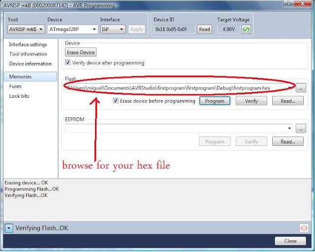
hex file ready for upload
For The Non-Believers: Proof That This Works
And of course here is the program in action. The big bright light is a ghost…just kidding is the light coming from the the super bright led in my power supply (thanks Sparkfun :P)
